|
In France the elites of the time could not resist to the tentation to consider this new weapon suitable for most the missions of a modern war. The spirits were clearly in the mood of rationalisation and optimization of the resources. It is a possible and personnal clue to understand the French fuzes history : comparatively to the profusion of the German models, there were relatively less French fuzes families in use during WW1, with often similar shapes and with factory-modulable properties (for instance addition of a detonator to adapt to the TNT loaded shells, or of a small compressed gunpowder piece retarding the burst with some hundredth of a second).
Their relative polyvalence can make the French fuzes classification sometimes uneasy. For instance :
For this reason, the choice has been made to include in the instant effect fuzes of this study only the ones that allowed a real 'premature' explosion over the ground surface, and keep the other 'instant effect' fuzes having optionnal 'percussion' or 'delayed percussion' variants in the 'percussion fuzes section'. Also, we did not try to separate the trench artillery fuzes from the artillery fuzes.
Another French fuzes characteristic concerns the time and tima and percussion fuzes : France was the only country to prefer almost exclusively the tubular spiral type fuzes , while all other countries adopted the rotating discs types.
French WW1 fuzes models also differentiate themselves from some the other countries' ones by their relative simplicity and their low mass. Finally, compared to German fuzes, French ones are entirely made in noble metals (brass), proving this nation remained well delivered with minerals and metals by its allies and colonies throughout the war.
For this latter reason, the French fuzes that can be found nowadays on battlefields or in collections are often less impressive by their mass than most of the other nations ones, but often in relative better condition, being less corroded than the German fuzes using more and more cheap material with the maritime blocus going on.
One final - and potentially lethal - characteristic of the French fuzes is the presence, for the ones designed after the introduction of modern high explosive shells replacing gunpowder shells, of a screwed or sometimes integrated small detonator at the end of the tail, filled with a small quantity of unstable explosive stuff. They were to provoke the detonation of a bigger primer inserted in the shell. These small detonators are sometimes still attached on the fuze that can be observed in ancient battlefields and remain dangerous even after more than 100 years.
The French fuzes denominations are simple and relatively well normalized, indicating most of the time the available function and properties, the external diameter of the fuze at the junction with the shell, the one of the tail thread, the year of the design and/or revision, and often the name of the designer (person or company).
Desmarest percussion fuze Mle 1859 |
||
 |
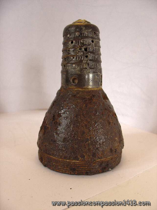
The presence in this section of this rudimentary fuze that was not in use in WW1 only makes sense because it gives a good starting point for the story of the French percussion fuzes used during WW1. Appearing in 1859, the Desmarest percussion fuze was mounted on the 4, 8 and 12 shells that were shot during the 1870 short war opposing France and Germany. |
|
22 mm Desmarest fuze. The profile looks like a simple nutscrew with hexagonal head. This item is dated 1875. |
||
 |
 |
|
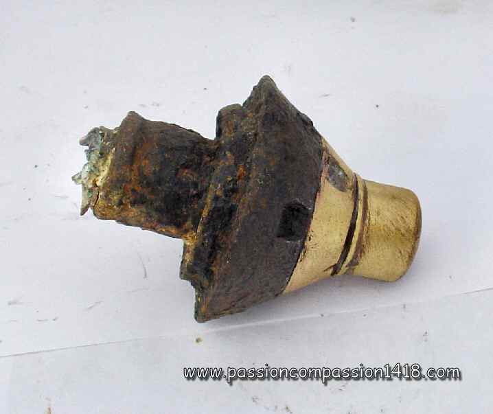
22 mm Desmarest fuze. This view shows the cylindric central room, the top wood plug is missing. |
22 mm Desmarest fuze. Top view : there are some wood remains inside the fuze body. |
|
 |
 |
|
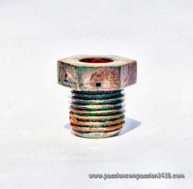
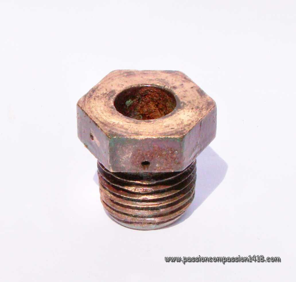
22 mm Desmarest fuze. Rear view with the central vent communicating the flame to the shell, and the two holes for the screws attaching the inner wood piece bearing the primer. |
22 mm Desmarest fuze. Rear view, notice the lateral hole inside the hexagonal head for the nail fixing the top wooden plug. |
|
 |
||
Desmarest fuze. Vintage scheme. |
||
Back to the top of the page |
||
25/38 Henriet fuze Mle 1874/75 |
||
 |
During the last XIXth century decades, the artillery was subject of a very quick technological evolution applied also to the ammunitions and fuzes. In France, after the very rudimentary direct action fuzes came the very first inertia percussion mechanism fuzes such as the Tardy (1860), Double Réaction (1865), Friction Tardy (1870) and Maucourant (1876) systems.
At the shot start inside the barrel, the safety spring in the graze pellet was compressed by the recoil force, allowing the inertia block to move back and unmask the friction pin tip. This tip opened the brasse blades and was kept in this position by themd was the block was clipsed in this postion by them, arming the mechanism. In flight, only the protective membrane was preventing an accidental explosion. At the impact on a target, the inertia block propulsed the percussion pin to the front. This one was easily peircing the protective membrane and triggered the primer. The created flame was communicated to the gunpowder room and amplified by it, then directed to the tail rear through the vent, triggering the shell ewplosion. The Henriet fuzed was arming the olds a 5 and 7 explosive shells, but also the explosive shells more modern 80, 90 et 95 mm fieldguns, aa well as those of the 138mm siege gun. It was interchangeable with the 'fusée Budin Mle 1875 ', and these obsolete fuzes were very likely used with old shells stoks shot with these old guns coming back from arsenals durig the first period of WW1. |
|
25/38 Mod 74/75 Henriet fuze. Notice the side hole in the thread, bored in order to allow the communication between the top of the gunpowder room and the percussion system. Its position permits to see the difference with a 74/75 model equipped with an elongated room. |
||
 |
 |
|
25/38 Mod 74/75 Henriet fuze. Rear view with the almost central vent of the percussion system and the more exentric hole of the gunpowder room |
||
 |
||
25/38 Mod 74/75 Henriet fuze. Marking '75' gives the 1875 manufacturing year |
25/38 Mod 74/75 Henriet fuze. Front view with the exentric upper screw of the percussion system. |
|
 |
||
25/38 Mod 74/75 Henriet fuze at the side of the Budin fuze with the same profile |
||
 |
||
25/38 Mod 74/75 Henriet fuze. Modern sheme showing the arming sequence using the brass blades staple and the percussion sequence on the target. Notice the gumpowder room parallel to the percussion mechanism room, typical of an original Mod 74. |
||
Return at the top of the page |
||
Budin fuze 25/38 Mle 1875 |
||
 |
The years after the 1870 war, that had seen the Armies of the French Emperor Napoleon III being defeated by those of the young German First Reich, coincided with numerous developments of military technologies, particularily in the artillery domain, therefore in the fuzes technology as well.
The old percussion fuses Desmarest (1859) and Tardy (1860) were progressively replaced by a new generation of more sophisticated devices. The principles of those new percussion systems Henriet (1874), Budin (1875), Siège et Montagne (1878), Saussier (1887) et Robin (1888), equipped with more and more reliable safety, arming and percussion mechanisms, were afterwards used in the XXst century fuses. The bronze Percussion fuse of 25/38 mm System Budin, model 1875 presented here was invented by the Lieutenant Budin. It seems to be inspired from the 1874 Henriet fuze whose principle has been globally kept (including the bras blades staple arming system), but shows three major modifications that provided new standards :
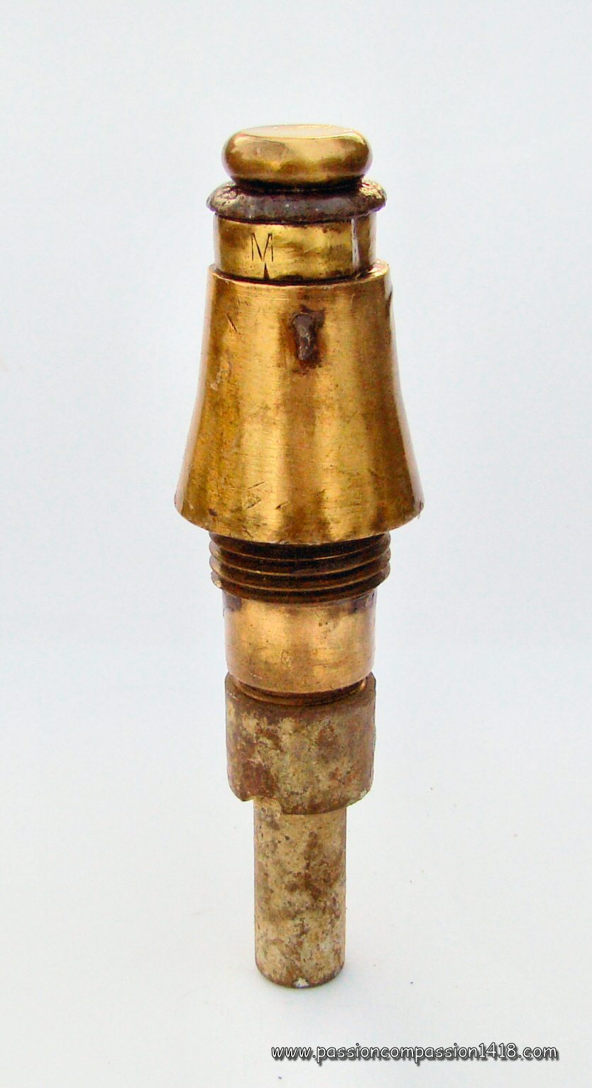
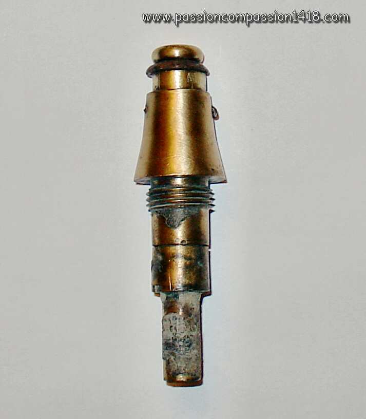
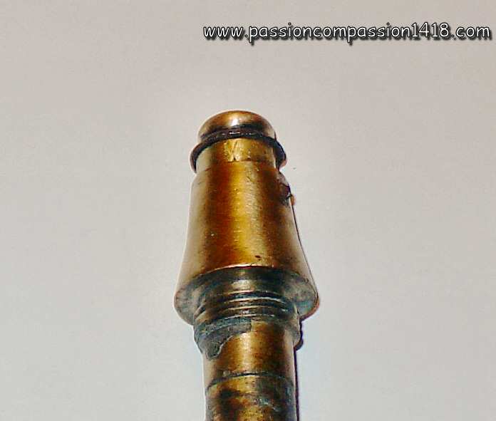
At the shot start, the inertia forces was violently pushing the mobile graze pellet backwards, pressing the brass blades and letting the percussion cap block entering entirely inside the central room of the block. Once unmasked this way, the primer was only separated from the friction pin by the safety spring during the flight time, and the shell was armed. When hitting the target , the solidary ensemble mobile inertia block / percussion cap was propulsed towards the front, compressing the safety spring and came in contact with the percussion pin, triggering the shell burst under the action of the gunpowder room flame under the primer. The fuze top plug bearing the friction pin was machined with a circumference rupture groove, allowing the head to fracture at this level at the impact without influence on the below percussion mechabism. When this fuze was armed, a simple cm fall was enough to trigger its burst. Two modifications (1879 for the Navy, and 1881 for the Army) are known and indicated on the fuze body by a 'M' stamp. The Budin fuze was arming the olds a 5 and 7 explosive shells, but also the explosive shells more modern 80, 90 et 95 mm fieldguns, aa well as those of the 138mm siege gun. It was interchangeable with the 'fusée Henriet Mle 1874 et 1874/75 ', and these obsolete fuzes were very likely used with old shells stocks fired with these old guns coming back from arsenals durig the first period of WW1. |
|
25/38 Mod 75 Budin fuze. Markings : 'CP - 74', and two small 'B' on the cone top. It is an enigma to me that this item hs been built in 1874 (before the 75 mod adoption date ?)... |
||
 |
 |
|
25/38 Mod 75 Budin fuze. Wartime scheme. |
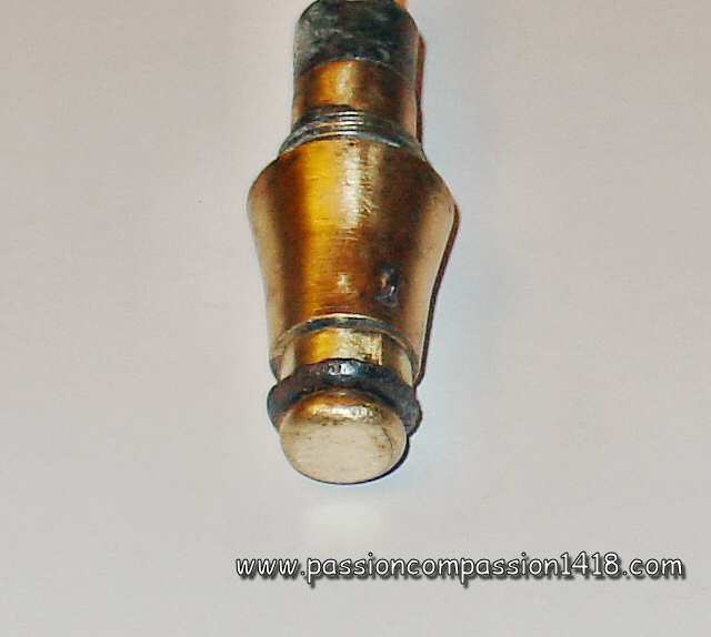
25/38 Mod 75 Budin fuze. Top view with the large head plug |
|
 |
||
25/38 Mod 75 Budin fuze. These 5 items markings show several manufacturing years ('74', '75', '76' et '77'). |
||
 |
||
25/38 Mod 75 Budin fuze. Top view |
||
 |
||
Budin percussion system (extracted from a 25/38 Mle 1880 time and percussion fuze) |
||
 |
||
25/38 Mod 75 Budin fuze. Rear view of two pieces showing the flame communication channel from the gunpowder room |
||
 |
||
25/38 Mod 75 Budin fuze. Vintage scheme shomwing the arming sequence |
||
Back at the top of the page |
||
Fuze for 37 mm and 47 mm shells Mle 1877 |
||
 |
In 1877, the Frech Army and Navy choose a miniaturized version of the 22 mm Mle 1859 Desmarest fuze for the 37 mm and 47 mm pig iron shells.
Apart from the reduced dimensions, the very simple inner mechanism of the initial Desmarest system was kept with the pushable wooden plug bearing the percussion pin, protected by a gum varnish layer and attached to the fuze body by nails, and the rear wooden piece holding the primer, fixed by pins, linked to the shell body by a drilled communication vent through the brass bottom and protected by a paper sheet. The 25 Mle 1877 percussion fuze for 37 mm and 47 mm shells, system Desmarest profile was reduced proportionnally to adapt to the small 37 mm and 47 mm shells with a 13.5 mm tail thread, and the head was given a tronconic shape whose angle was related to the shell ogive instead of the hexagonal shape of the original fuze. A tin washer was providing the safe link between the fuze and the shell. The Desmarest Mle 1877 fuze was used with the explosive projectiles of the
|
|
Mle 77 Desmarest fuze. Markings 'L4 7 4 16'. notice the tin washer. |
||
 |
 |
|
Mle 77 Desmarest fuze. Front view on the wooden block protection. |
Mle 77 Desmarest fuze. Rear view on the flamne vent |
|
 |
 |
|
Mle 77 Desmarest fuze. View on an item still attached to its 37 mm shell. The wooden plug protection has disappeared and remains of wood can still be seen |
Mle 77 Desmarest fuze. Modern scheme |
|
Return to thz top of the page |
||
25/38, 30/45 and 40/55 S.M. fuze Mle 1878-81 and 1878-92 |
||
 |
Designed in 1878 for the Siege and Mountain artillery ('S.M.'), whose bell-type trajectories setting needed the use of variaiable propulsive charges quantities that did not permit to ensure the arming of the usual percussion fuzes Budin or Henriet, the bronze fusée percutante Siège et Montagne (S.M.) modèle 1878 was built to be armed with the same safety standards whatever the initial speed given by the propulsive charge value. Moreover, its sensitivity allowed to provide a normal function at the arrival on the target even for relatively low speeds.
In order to reach this specicication, several modifications were provided to the classical percussion Budin system with mobile primer-bearer inertia block, safety spring and brase blades staple arming device :
These characteristics were at the origin of the choice of this fuze for equipping the projectiles of the very first reglementary French trench mortars, awaiting for the arrival of specific devices. The Siège et Montagne percussion fuze was mainly used with the explosive shells of the
Many variants of that fuze are known, either due to modifications of their inner mechanisms (identified by the design year) or by their shape : Inner mechanism variants :
Profile and thread size variants (for adaptation to different shells) :
|
|
25/38 Mod 78 Siège et Montagne fuze. Original model. Markings : '78'. Notice the considerable elongation of the tail compared to the previous fuzes types, necessary in order to include the double arming system. |
||
 |
||
Different variants of Siège et Montagne fuzes. Top view allowing to indentify the various variants : mod. 1878 (without plug), 1878/81 (large plug) and 1878/92 (narrow plug). |
||
 |
 |
|
30/45 Mod 78-81 fuze. Several items including one still having a part of the shell |
30/45 Mod 78-92 fuze. Several items including two still having a part of the shell |
|
 |
 |
|
30/45 Mod 78-81 fuzes observed at Massiges (Champagne). Notice the exploded tail and shell envelopes. The visble thread is the one of the detonator ECP 12-14 in wheich the fuze tail was inserted. Markings : '30 45' - 'Mle 78 81' - '82' - 'ECP R 6 08' |
30/45 Mod 78-81 fuze. Top view. Red paint traces at the bottom of the threads, typical of the mod 81 not modified 1915 (black paint). Markings : '81' |
|
 |
||
30/45 Mod 78-92 fuze. The '92' variant, that can be identified with its narrow plug, that has been partially ejected by the explosion. These models are less easy to find. |
||
 |
||
Different variants of Siège et Montagne fuzes. Rear view showing the different tail configuration; with simple vents for tyhe models 1878/81, and large tail plugs for the models 1878 and 1878/92. |
||
 |
||
Different variants of Siège et Montagne fuzes, and different threads. From left to right, 35/38 Mle 1878/92 (unusually with a thread adaptor on a 25/38 type), 30/45 Mle 1878/81, 25/38 Mle 1878/81, 25/38 Mle 1878, and 30/45 1878 (/92 ?). |
||
 |
 |
|
30/45 Mod 78-81 fuze. This item is still on the shell remainings : a French 'mushroom' as nicknamed by the battlefield visitors, part of a medium caliber shell (as shown by the wall thickness), observed in Massiges (Champagne) |
30/45 Mod 78-81 fuze. Wartime scheme. The rupture groove machined in the head plug was introduced with the Budin fuze and was made to keep the lower mechanism of the fuze intact, including the percussion pin, if the impact shock energy was big enough to break the fuze head |
|
Return at the top of the page |
||
Percussion fuze 24/31 Mle 1899 and 1899-08 |
||
 |
The inertia percussion system with brass blades staple safety was subject to a new evolution in 1886 with the design known as the Robin system (name of its inventor). Starting from the 1875 Budin system used in the 25/38 Mod 1875 percussion fuze percussion fuze with a static percussion pin fixed under the head plug, and a mobile graze pellet bearing the primer and armed by a brass blades staples system, it was inheriting the improvements given in 1884 by the Saussier system used in the 30/38 Mod 1884 time and percussion fuze.
Briefly introduced by the Navy in its 18/28 Mle 1886 time and percussion fuze for 65mm shell, this new Robin system became famous with the 22/31 mm percussion fuze without detonator Mod. 1888, system Robin. It was introducing major evolutions, including :
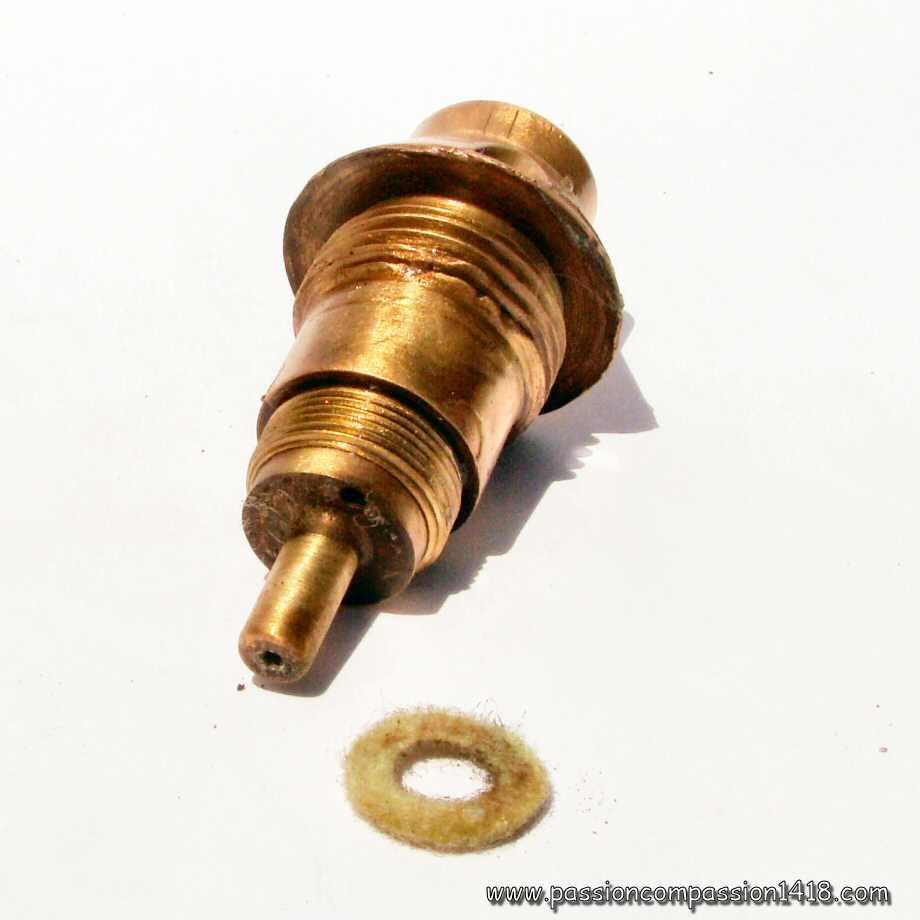
The most famous fuze that inherited this system was the 24/31 mm percussion fuze with detonator Mod. 1899 System Robin-Lejay, the first of the French percussion fuzes designed with an integrated detonator for the use on high explosive shells (not filled with gunpowder), and classical device used with French WW1 explosive shells of most calibers in August 1914. The fuze was divided in three different parts :
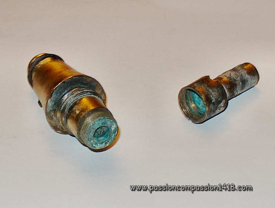
In 1914, the French Army had to admit soon that the artillery fire had to be made most of the time at a range too long to allow such tangeant fire. Consequently the original model non-delay fuzes were used again. Both variants cannot be differentiated externally, unless if the safety steel cap paint is still visible ; white vernish for the delay-free original Mle 99 fuze, and black vernish for the delayed Mle 99-O8 fuze, or thanks to the rear tube shape. |
|
24/31 Mod 99 or 99-08 fuze. |
||
 |
||
24/31 Mod 99 or 99-08 fuzes. This kind of fuze remnants such as the ones at the left can often be seen on ancient WW1 battlefields |
||
 |
 |
|
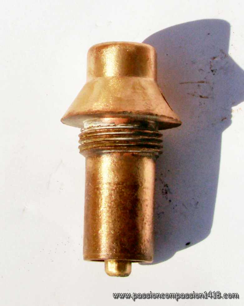
24/31 Mod 99 or 99-08 fuze. Three entire items, with their detonator attached |
24/31 Mod 99 or 99-08 fuze. At the left an unusual specimen on which the Lejay system cap is made in brass instead of steel. |
|
 |
||
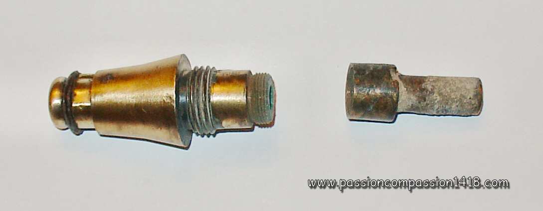
24/31 Mod 99 or 99-08 fuze. Detonator removed |
||
 |
 |
|
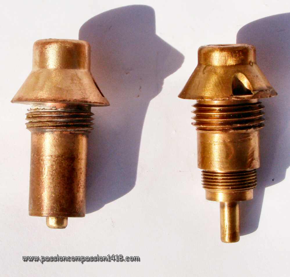
24/31 Mod 99 or 99-08 fuze. Rear view showing the arming staple blades Vand the mobile arming mobile inertia block with the two external shouldres, removed from its room inside the fuze. |
24/31 Mod 99 or 99-08 fuze. Cap removed (picture Luc Malchair) |
|
 |
 |
|
F24/31 Mod 99 or 99-08 fuze. Cut-through showing the Lejay system inside the fuze head cap |
24/31 Mod 99 or 99-08 fuze. Note the original paint markings traces as well as the groove at the top tof the cap that allowed to unscrew the Lejay arming system |
|
 |
 |
|
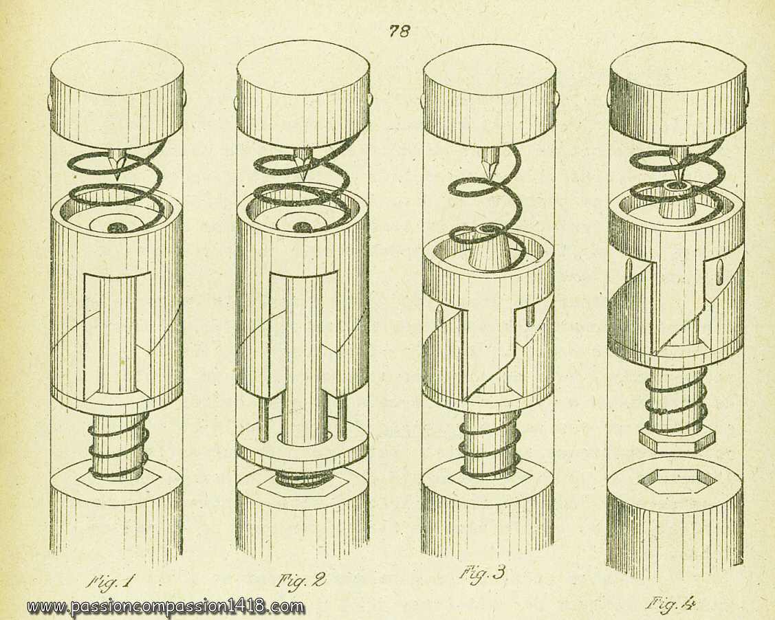
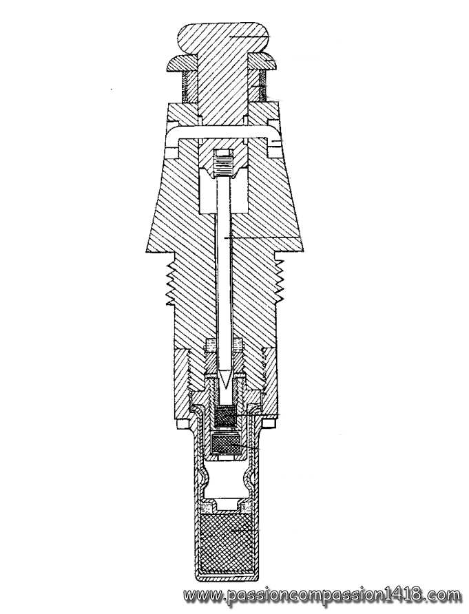
24/31 Mod 99 or 99-08 fuze. Wartime scheme showing marking types. |
24/31 Mod 99-08 fuze (with 0,05 s delay). Wartime scheme |
|
Return at the top of the page |
||
Percussion fuze 24/31 Mle 1899-1915, systeme Robin |
||
 |
The use of the 24/31 Mle 1899 and 1899-08 percussion fuzes was presenting some issues in particular situations :
The new fuze was still keeping the 'Robin' percussion system of the 1899 and 1899-08 fuze, contained in a brass tube whose lower part was very similar, while the tronconic (with a right angle bevel at the base) upper part was more massive (and therefore more resistant), and did not integrate the 'Lejay' safety system for the percussion pin that was now fixed to a simple head plug. In the 24/31 mm percussion fuze with detonator, model 1899-15 (second model), system Robin that came shortly after, the fuze head plug to which the percussion pin was attached replaced by a much smaller one (its diameter becoming similar to the one or the percussion pin) so that the fuze head was even more massive and resistant. Three versions of both these models were existing, depending on the optionnal integrated delay value :
A last variant with steel body and a short delay was also introduced in 1916 for the anti-tank fire, with a hemi-spherical head painted in yellow. This fuze was used with various calibers high explosive shells of many guns and mortars :
|
|
24/31 Mod 99-15 fuze. |
||
 |
||
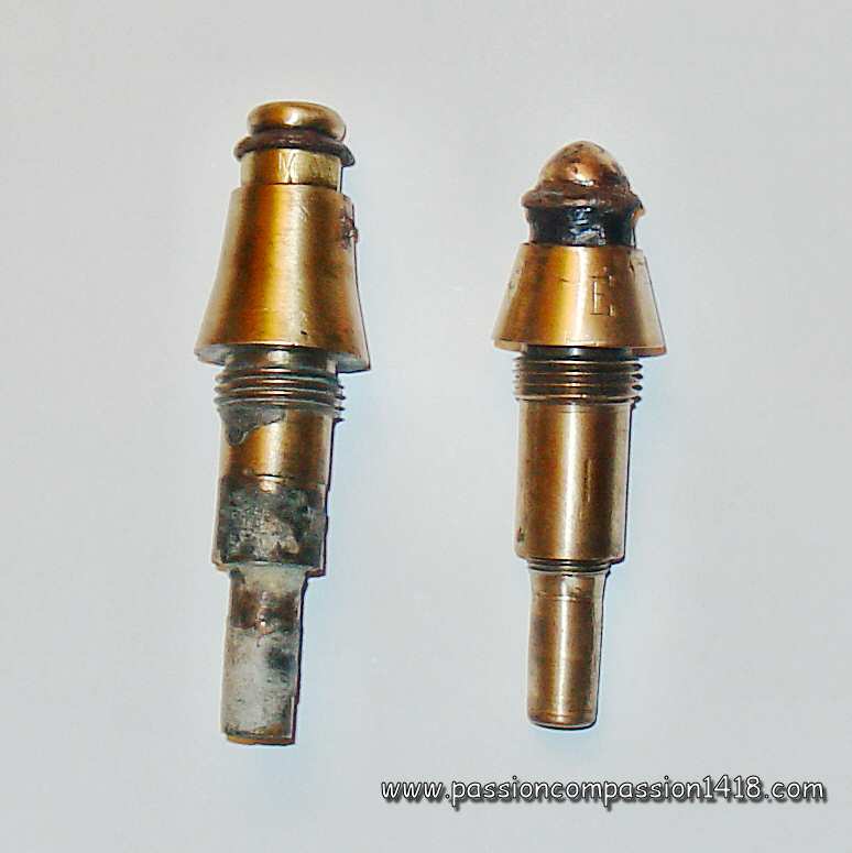
24/31 Mod 99-15 fuzes. First model (at left) with the large head plug and remains of black paint indicating a non-delayed fuze, and second model (at right) with the small head plug |
||
 |
 |
|
24/31 Mod 99-15 fuzes. Side view of a first and a second model, unstinguishables. |
24/31 Mod 99-15 fuzes. First and second models, tail detonators removed |
|
 |
 |
|
24/31 Mod 99-15 fuze. Phicture courtesy Luc Malchair |
24/31 Mod 99-15 fuze. Modern scheme (secon model with small head plug |
|
Return to the top of the page |
||
Mod 1915 Schneider fuze for 105 mm shells |
||
 |
Usually restricted to the French Army arsenals such as the Ecole Centrale de Pyrotechnie, the design and manufacturing of the WW1 French fuzes was extended to some private companies, whose artillery weapons designed for exportation were progressively adopted by the Head Quarter.
This is how the adoption of the good 105mm Mle 1913 fieldgun of the Etablissements Schneider in Le Creusot (Burgundy) opened the door to the delivery by the same company of ammunitions and fuzes of its own design too. This explains why these devices not designed in the usual arsenals sometimes integrate radically different technological choices. This is the case with this brass Schneider percussion head fuze M 1915 with detonator for middle caliber shell, that was atypical for several reasons :
The ingenious percussion system designed by Schneider was functionning thanks to inertia and its arming was based on both inertia and spin. It was composed of a static percussion pin, separated from a primer-bearing heavy graze pellet by a safety spring. This pellet movements were prevented at rest by segments pushed inside a groove machined on the pellet by a spring wrapped around them. A cylindric safety ring was pressed against the upper part of the pellet room by a ring spring. A the shot departure, inertia forces pushed back the safety ring around the segments, compressing its spring. As long as the acceleration was continuing, (in the barrel), The segments were not able to spread despite the shells spin and the fuze was secure. At the muzzle exit, the acceleration stopped, and the ring spring was pushing up the ring. This allowed the segments to spread under the effect of the centrifugal force that was ellarging the spring wrapping them. The graze pellet movements were now only prevented by the safety spring palced between the percussion pin and the primer carp. At the impact, this spring was easily compressed by the arrival shock propulsing the pellet frontwards and provoking the explosion. The primer flame was transmitted to the tail detonator (Schneider type) through a vent. This percussion system was reproduced, with a scale factor, in the several 24/31 Mod 1916 Percussion fuzes system Schneider. Located in the fuze head top under a threaded plug, the additional pyrotechnic safety system was acting like most of the German fuzes systems ; at the shot departure, a concutor was hitting a small primer igniting a gunpowder pellet. The combustion of this pellet freed the movements of a piston that was maintaining at rest the heavy graze pellet and was also masking the tip of the percussion pin. The fuze was hermetic and the absence of any combustion gasses escape vent was compensated by an inner reservoir room. This fuze was excluvely used with the high explosive shells of the
Alternative accentuated conical shape versions have been observed on the battlefields (see pictures) but no relative information was found. |
|
Mle 1915 Schneider fuze for middle caliber shell. Associeted to the specific tail detonator made by Schneider as well (picture Luc Malchair) |
||
 |
 |
|
Mle 1915 Schneider fuze for middle caliber shell. View on the specific Schneider tail detonator (unscrewed) - Picture Luc Malchair |
Mle 1915 Schneider fuze for middle caliber shell. Another item observed in Champagne. Only the upper part survived : the 47,5 mm thread has been destroyed |
|
 |
 |
|
Mle 1915 Schneider fuze for middle caliber shell. Original version (at the right) together with the unidentified variant (at left) observed in Champagne. |
Mle 1915 Schneider fuze for middle caliber shell. Rear view that shows just like a cut-through at the level of the thread : both the variant and the original one seem identical viewed from below |
|
 |
||
Mle 1915 Schneider fuze for middle caliber shell. Two specimens : one is still mounted on a 105mm Schneider shell top remnant. Upper view with the screwed plug hiding the pyrotechnic safety |
||
 |
 |
|
Mle 1915 Schneider fuze for middle caliber shell. Side view of the two specimens; the shell burst almost expelled the left fuze from the steel ogive. |
Mle 1915 Schneider fuze for middle caliber shell. Wartime scheme |
|
Return at the top of the page |
||
24/31 Schneider percussion fuze |
||
 |
The Le Creusot Schneider plants know-how was famous throughout the world in various metallurgy and mechanics techniques, including artillery. Rather succesful in export markets before WW1, they participated to the French war effort by designing and manufacturing guns and ammunitions.
In 1916, Schneider proposed a new percussion fuze based on the percussion mechanism developped for its Schneider percussion fuze Mle 1915 for middle calibre shells, and supposed to replace the instant effect percussion fuzes 'I' Mle 1914 and 'I.A.' Mle 1915 or 'I.A.L.' Mle 1916 that were experiencing numerous issues. This 24/31 percussion fuze with detonator model 1916, system Schneider was entirely made of brass. Its shape was similar to the one of the classical French percussion fuzes using the 24/31 template as well as the profile of its most usual variants (Tracés A. 1644 B., A. 1772 and A. 1820 similar to the Robin-Lejay fuze Mle 1899; Tracés A. 1644 B.A. and A. 1853 similar to the Peuch fuze Mle 1914). In the inside, the fuze was using the percussion mechanism of the Schneider percussion head fuze M 1915 with detonator for middle caliber shell with smaller scale dimensions, with the same two-steps arming mechanism by inertia (ring) et centrifugal force (segments), but withoiut the additional pyrotechnics armin system. Since the mechanism could only be armed by rotation speeds > 12000 turns/minute, this fuze could only be used with the projectiles of the 75mm Mle 1897 fieldgun. The attached explosive charge was again a 2 grams fulminate detonator. The fuze was existing in 2 versions : one without delay (head painted in white), and one with a small 0.05s delay (head peinted in black). The same base was used for several fuzes, whose most known ones, named by their Schneider's catalog 'numéro de Tracé' (dramwing number) were :
|
|
Schneider Fuze Mle 1916 Tracé A. 1644 B. Notice the profile similar to the 24/31 Robin/Lejay Mle 1899 fuze |
||
 |
 |
|
Schneider fuze Mle 1916 Tracé A. 1644 B. A first evident difference with the 24/31 Mle 1899 fuze is the head cap in brass instead of steel and not screwed to the body. |
Schneider fuze Mle 1916 Tracé A. 1644 B. Another major external differnce with the 24/31 Mle 1899 can be seen with the tail detonator whose male thread is inserted inside a brass adaptator ring. |
|
 |
 |
|
Schneider fuze Mle 1916 Tracé A. 1644 B. This specimen still shows some white paint traces that designate a non-delayed variant |
Schneider fuze Mle 1916 Tracé A. 1644 B. Zoom on the top cap with the hole containing the pin that was holding the percussion pin holder in position |
|
 |
 |
|
Schneider fuze Mle 1916 Tracé A. 1644 B. (top) and Schneider fuze Mle 1916 Tracé A. 1853 (bottom). In addition to the evident head cap height difference, notice the tail profile difference, the tail detonator fixing difference, and the joint difference between the head cap and the body, typical to the two main families |
Schneider fuze Mle 1916 Tracé A. 1772 or 1820. The scewed head typical of this family is almost removed by the shock. |
|
 |
 |
|
Schneider fuze Mle 1916 Tracé A. 1853. This time the profile is similar to the one of the 24/31 'I' Mle 1914 fuze |
Schneider fuze Mle 1916 Tracé A. 1644 D. ter. of 24/40.5 mm. These fuzes profile is completely different, with a very specific conical head. |
|
 |
 |
|
Schneider fuze Mle 1916 Tracé A. 1772 or 1820. on a 75 mm shell ogive |
Schneider fuze Mle 1916 Tracé A. 1772 or 1820. wartime scheme |
|
Return to the top of the page |
||
24/31 Mod 1916 'P.R.' percussion fuze |
||
 |
In 1916, Captain Remondy improved the helicoidal ramps safety system of the 24/31 Mod 1914 percussion fuze system Peuch, in order to make it compatible with the projectiles and firing conditions of the trench mortars.
In this new new version, logically taking the name 24/31 Mle 1916 percussion fuze, system Peuch-Remondy, the designer was introducing several improvements. As a first noticeable one, the head system with a mobile percussion-pin bearing plug pressed against the inner room by steel balls was replaced with a simple massive head including the percussion pin. This characteristic made the fuze particularily robust and less sensitive to humidity, therefore better adapted to the tough conditions of the trench artillery. The safety device with rear inertia block, helicoidal ramps mobile inertia block with primer cap and the separated safety section masking the primer was also slightly modified. Whereas the upper mobile safety section was kept similar with its diagonal-ramps cut teeth, this time the lower mobile inertia block was composed of a symetrical hollow section with the opposite diagonal-ramps cut teeth, and the primer cap was now located in a new distinct central cylinder around which the upper and lower sections could slide and equipped with lateral studs whose faced were machined to adopt the shape of the space between the two helicoidal ramps of the upper and lower sections. This new safety device allowed an arming process in two steps :
|
|
24/31 P.R. fuze Mod 1916 with its tail detonator. This fuze made for low accelerations is still particularily sensitive and dangerous. |
||
 |
 |
|
24/31 P.R. fuze Mod 1916. Second model with the head top small hole for the percussion pin insertion. This one is mounted on the upper part of a trench artillery bomb through a specific adatator. |
24/31 P.R. fuze Mod 1916. Detonator removed (empty) - picture Luc Malchair |
|
 |
||
24/31 P.R. fuze Mod 1916. Initial model with plain head at the right, and second model with small head hole at the left. Both items are still attached to the remains of a trench artillery bomb that has been flattened by the explosion, but recognizable by their thin steel walls. |
||
 |
 |
|
24/31 P.R. fuze Mod 1916. Paint markings remains on the cone |
||
 |
||
24/31 P.R. fuze Mod 1916. Wartime scheme explaining the inner mechanism arming sequence |
24/31 P.R. fuze Mod 1916. Wartime scheme with a zoom on the helicoidal ramps |
|
Return to the top of the page |
||
24/31 'I' fuze Mle 1914 system Peuch |
||
 |
In 1914 a new fuze was introduced, designed by the Workshop Manager Peuch of the French 'Ecole Centrale de Pyrotechnie'. Even if the shape and proportions could suggest just a small evolution of the classical percussion fuzes 24/31 Mle 1899 et 1899-08 Robin / Lejay, it was indeed a completely different inner mechanism that was proposed, giving birth to the first instantaneous (or 'quick action' French fuze.
The fusée-détonateur percutante 'I' de 24/31 model 1914 ''I' Instananeous percussion fuze with detonator, system Peuch was inheriting several innovating devices that allowed it a very quick percussion action by inertia and push-back :
At rest, the upper safety mobile block and the lower mobile block were placed teeth to teet, held together by the two pins of the disc inertia bloc traversing them, and by a small transverse tin pin. The upper safety spring located between the upper mobile block and the percussion pin, as well as the smaller arming spring wrapped around the base of the primer-bearer rod below the disc-shape mobile block were also maintaining this assembly at an intermediate position. In that elongated configuration, the assembly was long enough to mask the central rod's upper peimer cap that was therefore kept unaccessible to the percussion pin. At the shot departure , the disc-shaped lower mobile bloc was violently pushed back, compressing the small rear arming spring and removing its two pins from the upper cylindrical teethed inertital block. The teethed inertia blocks were still held up for some tiny moments by the transverse tin pin, and the upper mobile block was given a rotating force under the action of the helicoidal cut teeth pressing against each other finally shearing the tin pin. The blocks then moved backwards, while the upper block rotation made the two block teeth mesh inside each other profiles. This was shortening the the two mobile blocks assembly, unmasking the percussion cap located at the top of the central rod. At the muzzle exit, with the disappearing acceleration, la masselotte arrière en forme de disque était repoussée vers l'avant avec sa tige sous l'effet de son ressort arrière, et formait dès lors avec les deux masselotes cylindriques un solidaire mobile autour de la tige mobile porte-amorce. The fuze was therefore armed, and during the flight only the upper safety spring was preventing the primer cap to be hit by the percussion pin. At the impact, the assembly made of the three inertia pieces was violently propulsed frontwards, compressing the upper safety spring. The mobile rod was also propulsed to the same direction, making a contct between the primer cap and the percussion pin. As said before, the percussion pin could also in m8any cases be propelled towards the primer cap when the fuze head was hitting a resistant enough target. This system insured a much quicker triggering at the impact than the Fuze Mod 1899, exploding assurait un fonctionnement nettement plus rapide que la fusée modèle 1899, usually exploding as soon as the shell entered the ground only until the ogive level, suitable for uses where the anti-personnal effects were needed,and therefore deserving its classification in the 'instantaneous' fuzes. This fuze plug was usually painted in red, sometimes in white or blue instead. The 24/31 'I' Peuch fuze was mainly used with high explosive, chemical or incendiary shells of the
However, these fuzes were not compatible with the conventional trench warfare artillery weapons such as the classical 58, 150 or 240 mm mortars, whose shot start energy was not sufficient to arm the fuze. |
|
24/31 Mod 1914 'I' fuze. Side view of the fuze easily recognizable shape and the detonator screwed to the tail end. |
||
 |
 |
|
24/31 Mod 1914 'I' fuze. Another very common artefact that can be seen on former battlefields. Most of the fuzes that ca be observed on the ground have lost their push-back system head plug |
24/31 Mod 1914 'I' fuze. View on the head plug of two similar items, one of them kept traces of its original red paint |
|
 |
||
24/31 Mod 1914 'I' fuze. The tail detonator has been unscrewed, notice the long tube for the pyrotechnic relay charge. |
||
 |
 |
|
24/31 Mod 1914 'I' fuze. The tail detonator has been unscrewed, rear view on the pyrotechnic relay tube, and a remaining fedora disc. |
24/31 Mod 1914 'I' fuze. Nice item still attached to an adaptator that was probably used for 155 mm shells. Notoce the head plug that seems to have been pushed back at impact |
|
 |
 |
|
24/31 Mod 1914 'I' fuze. Wartime scheme explaining the arming process |
24/31 Mod 1914 'I' fuze. Wartime scheme |
|
 |
||
24/31 Mod 1914 'I' fuze with adaptator and a shell detonator (empty). Red paint traces are still visible. |
||
Return at the top of the page |
||
22/31 'I' Mle 1915 system Peuch for Naud shell |
||
 |
A variant of the 24/31 Mle 1914 'I' Peuch percussion fuze was introduced in 1915, with the same inner mechanism but with a modified body to make it compatible with the 30/38 mm shell detonators of the Naud type chemical shells loaded with phosphorus.
This '22/31 mm Mod 1915 percussion instantaneous fuze' was also very useful for the use with old obsolte high explosive shells having a small 22 mm thread ogive hole. This fuze was mainly used with the high explosive, chemical or incendiary projectiles of the
|
|
22/31 'I' Mle 1915 fuze. |
||
 |
 |
|
22/31 'I' Mle 1915 fuze (at left) compared to a classical 24/31 'I' Mle 1914 fuze that came first, in order to compare the profiles main differences : longer head and longer tail. |
22/31 'I' Mle 1915 fuze. Rear view on the shell detonator (rmpty) with some markings |
|
 |
 |
|
22/31 'I' Mle 1915 fuze. Another comparaison with the 24/31 Mle 1914 fuze. Both heads seen from the top are similar. |
22/31 'I' Mle 1915 fuze. Another comparaison with the 24/31 Mle 1914 fuze. |
|
 |
 |
|
22/31 'I' Mle 1915 fuze. Equipped with the detonator for Naud shells (empty) |
22/31 'I' Mle 1915 fuze. Wartime scheme |
|
Return to the top of the page |
||
'I.T.' fuze with or without delay for trench artillery |
||
 |
After a first year of improvising starting in the end of 1914, leading to the creation of the 58 Nr1 trench mortar in January 1915, the French trench artillery is equipped in spring 1915 with the first reglementary materials with the 58 nr1 bis and 58 nr2 trench mortars.
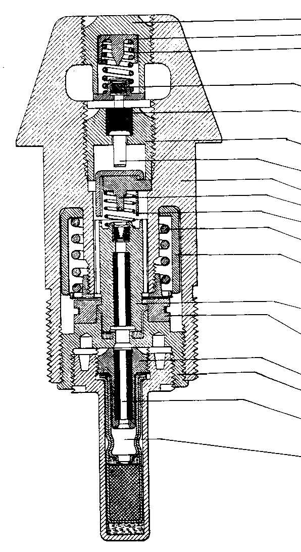
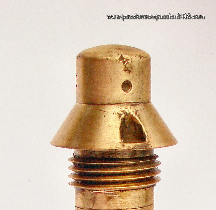
A simple quick action fuze is soon created to arm the fin tailed bombs of differnt sizes, and replace the momentaneous use of the Siège et Montagne fuze that was initially used with the 58 Nr1. trench mortars This 24 mm 'I.T.' Mod. 1915 instantaneous stem fuze with or without delay for trench artillery ('I.T.' for 'instantanée de tranchées' - Trench Instantaneous) was really basic, but proveed itself very efficient for its planned use, thanks to the long rod it was adding to the top of the trench mortars bombs in order to have is exploding before the main body hits the ground. The inner organisation was absolutely simple, with a rigid percussion rod guided inside a wooden cylinder inserted in the tubular stem body of the fuze. At the top end, this rod was linked to a mushromm shaped push button in aluminium, traversed by a soft metal pin. At its lower end, the percussion rod was turned into a percussion pin placed in front of a primer cap. The only safety device of this very simple fuze was the soft metal pin, strong enough to resist the bomb start acceleration and the air pressure on the mushroom-shaped push button, but easily sheared by the the aluminium head when it was hitting the target surface, intantaneously pushing back the rod and making the percussion pin hit the primer cap located at the fuze bottom and detonating the bomb via an usual 2 grams fulminate tail detonator and a shell big setonator. This fuze is known in two variants :
At rest, the fuze head was protected by a tin hat, and a brass ring preventing any movement of the push-back button during the transport. It had to be removed before use. The 'I.T.' fuze was mainly in use with the bombs of the
|
|
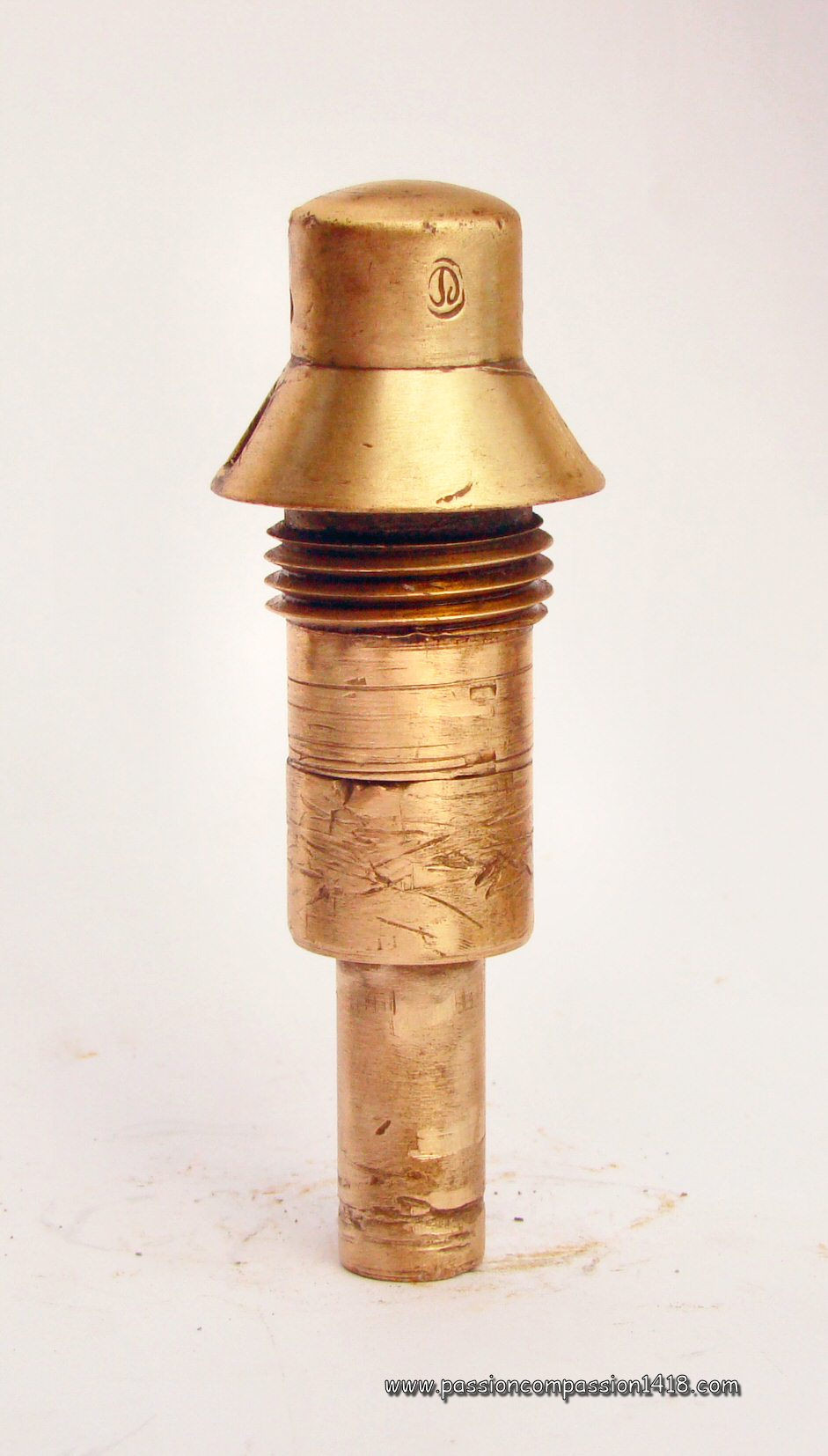
I.T. Mod 1915 delayed fuze |
||
 |
||
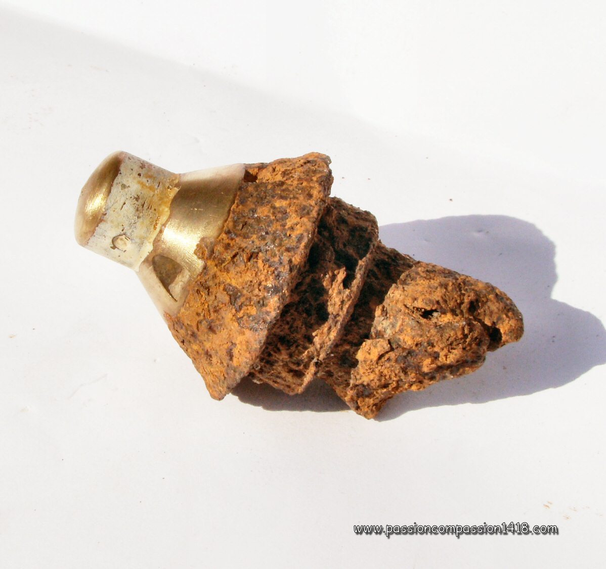
I.T. Mod 1915 fuze for trench mortar. Tweo items. The one on the top still owns its mushromm-shaped aluminium push-button while the one of the below fuze has disappeared. |
||
 |
 |
|
I.T. Mod 1915 fuzes for trench mortar. The space between the tail detonator and the fuze bottom is larger for the item on top, indicating a delayed model. The one below could the be a non-delayed model. |
I.T. Mod 1915 fuze for trench mortar. rear view with the standard tail detonator. |
|
 |
 |
|
I.T. Mod 1915 fuze for trench mortar. Mounted on a 16kg (or LS) bomb head, whose diamter was around 140 mm |
I.T. Mod 1915 fuze for trench mortar. Wartime scheme of the delayed and non delayed models. |
|
Return at the top of the page |
||
'I.A.' modèle 1915 and 'I.A.L.' model 1916 fuze |
||
 |
The 'I.A.' Model 15 fuze ('instantanée allongée') appeared in 1915, designed to obtain even quicker explosions when touching the ground than with the 24/31 Mle 1914 'I' Peuch fuze. In order to achieve that, the percussion mechanism of the I.A. fuze was located at the very top of a 12 cm long brass rod, and the transmission of its flame to the shell was insured by nothing less than a detonating chord (tin tube filled with melinite).
This percussion mechanism was included inside a steel body at the top of the bass rod, and consisted in a mobile percussion pin attached to a top head steel push-button and a static primer cap, without any safety spring to separate them from each other. At impact time, the push button was pushed back violently and had the percussion pin hit the static primer cap. The ignition of this one induced tye explosion of a small powerful detonator located in the head, that triggered the long melinite detonating chord. This latter was instantaneously provoking the explosion of a fuze tail detonator. At rest this fuze was secured by three systems :
At the muzzle exit the shell rotation speed became constant and allowed the centrifugal force to eject the small steel inertia section located at the external end of the brass spiral, unwrapping this latter, and finally ejecting the half rings, arming the fuze. In flight, the tin shear pin only was preventing the percussion pin to enter in contact with the primer cap, despite the air pressure against the button. At impact on the target the push-button was violently pushed back with enough force to easily cut the sagety shear pin, allowing the percussion pin to hit the primer cap. There was two models with opposite brass spiral wrapping directions :
As a consequence of numerous firing accidents, a modified 'I.A.L.' Model 1916 was manufactured afetr the works of André Lefèvre, Auxiliary Engineer of the Powders, and specialist of the primer caps detonation transmission. Noticeable differences could also be seen in the shape of the mushroom-shapes pushbutton at the top of the long fuze, as well as in the thread type of the tail (female for a male threaded detonator for the 'I.A.' model, male for a female threaded detonator for the 'I.A.L.' model). The I.A. and I.A.L. fuzes were mainly in use with the high explosive shells of the :
They remained subject to unwanted explosions whenever braking suddenly inside the barrel of the gun, and their shape influence on the shell's aerodynamics was affecting the range so much that it had to be taken into account in a specific table. |
|
I.A.L. fuze Model 1916 |
||
 |
||
I.A. fuze Model 1915 and I.A.L. fuze Model 1916. The two successive versions side to side with (blow) the I.A. Mle 1915 fuze, and (above) the I.A.L. Mle 1916 fuze. They can be recognized by small differences that are detailed in the two pictures below. |
||
 |
 |
|
I.A. fuze Model 1915 and I.A.L. fuze Model 1916. The 1915 version I.A. (right) is identified by its male threaded detonator, while the 1916 I.A.L. version has a classical female threaded detonator. |
I.A. fuze Model 1915 and I.A.L. fuze Model 1916. Another diference is the top button shape, massive and hemispherical for the 1915 version (above), flatter for the 1916 one (below). |
|
 |
||
fusée I.A. Mle 1915. Male threaded detonator and steel head removed |
||
 |
||
fusée I.A.L. Mle 1916. female threaded detonator and steel head removed |
||
 |
 |
|
I.A. fuze Model 1915 and I.A.L. fuze Model 1916. Steel top head bodies rear view |
fusée I.A.L. Mle 1916. This one suffered, but allows to see the flame channel through the brass body |
|
 |
||
fuze Model 1915 and I.A.L. fuze Model 1916. Wartime schemes |
||
Return to the top of the page |
||
T.C.A.L. Mle 1917 and 1918 fuze |
||
 |
The long profile of I.A. Mle 1915 and I.A.L. Mle 1916 fuzes was giving way to some inconveniences
Just as in this latter, the brass or steel rounded upper push button was linked by a long rod to the percussion pin that could hit a primer cap now located at the fuze body bottom, igniting the tail detonator. The T.C.A.L. fuze safety was provided by a triple system similar to the one of the I.A.L. one :
This fuze was mainly in use with the high explosive shells of the :
The slightly modified 1918 version and the original 1917 one were not recognizable externally, the main difference being the change of the tail pyrotechnic system (percussion pin - upper primer cap - primary primer - tail detonator for the T.C.A.L. Mle 1917 fuze; percussion pin - upper primer cap - tail detonator for the T.C.A.L. Mle 1918 fuze). |
|
T.C.A.L. Instantaneous fuze. |
||
 |
 |
|
T.C.A.L. Instantaneous fuze. Lefèvre safety system still in place. |
T.C.A.L. Instantaneous fuze. Top view. This item push button is in brass. Other ones had a steel push_button instead. |
|
 |
 |
|
T.C.A.L. Instantaneous fuze. Rear view. 'M' marking on the brass spiral above the push-button |
T.C.A.L. Instantaneous fuze. The tail detonator has been removed. Notice the tip of the percussion pin showing up at the base of the fuze body |
|
 |
||
T.C.A.L. Instantaneous fuze. The tail detonator (empty) has been removed. |
||
 |
 |
|
T.C.A.L. Instantaneous fuze. Accompanied at right by its post-war successor, the T.C.A.L. Mle 1926 fuze |
T.C.A.L. Instantaneous fuze. Modern scheme |
|
Return to the top of the page |
||
/
24/31 model 1917 RY fuze |
||
 |
The (Elongated instantaneous fuzes I.A. and I.A.L. and Elongated instantaneous fuze T.C.A.L.) equipped with a 'Lefevre' type arming system could only be armed under the action of a shell minimum spin speed. This was a limitation that induced the design of a new instantaneous system that was useable with projectiles indifferently of their rotation speed or direction, as well as in a large spectrum of initial speeds.
This how the Captain Remondy, already inventor of the 24/31 Mle 1916 'P.R.' percussion fuze, had accpted by the Army in 1917 a brand new quick action fuze that was fully answering to this need. This 24/31 mm RY model 1917 instantaneous percussion fuze, (RY as 'RemondY'), entirely made of brass and covered at rest by a crimped tin hat, using the conjunction of a purely inertia action arming system and a push-back percussion device. The hollow percussion pussh-button was placed at the top extremity of a long axial percussion rod bearing the percussion pin at its lower end. A strong percussion spring inserted in a room under the push-button was preventing the movements of this rod. the primer cap block was mobile and located at the base of the fuze tail. It was a long tube in which the percussion rod was able to penetrate and the primer cap was located at its lower end, out of range of the percussion pin at rest even if the percussion head was fully pushed back. The upper section of this tube was machined with two grooves. A tubular mobile safety inertia block was able to slide around the primer cap block upper section, and was equipped with three flexible brass blades staples whose extremities could grip the primer cap block grooves At rest the staples were gripping the primer cap block by the upper groove (named safety groove) and were held closed in this position under the action of a small mobile tubular inertia block around the mobile safety inertia block blades. An intermediate strength spring was keeping the small tubular block in upper position, and the mobile primer cap block in lower position. At the shot departure, at first the shell acceleration in the barrel was pushing backwards both the percussion head and the rod (compressing the strong percussion spring), whose lower percussion pin was closer but still out of range of the primer cap, and the mobile tubular inertia block (compressing the intermediate safet spring) and allowing the brass blades staples to open. This alloweed the second arming step, the tubular safety inertia block now being free to slide backwards under the action of the acceleration, until the brass blades staples were made to grip the lower groove (named arming groove). After this step the fuze was armed but still safe since the primer cap was held in bottom position under the combined action of the acceleration and the intermediate spring, out of range of the percussion pin. At the muzzle exit the acceleration stopped and the springs could act again : the strong percussion head spring was pushing back the percussion head and the rod forwards, putting again the percussion pin at longer distance from the primer cap. In the same time, the intermediate spring was pushing the mibile block forwards, with the brass blades staples blocked in the lower arming groove. In this configuration and with the intermediate spring neutralzed by the arming sequence, a third spring, of moderate force and located located between the bottom of the primer mobile primer cap block and the fuze tail end, was finally able to act and was pushing forwards the primer position that was now reachable by the percussion pin, hopefully kept in up position by the strong percussion spring. At the impact, the percussion head was violently pushed back, compressing the strong percussion spring and projecting the percussion pin at the contact of the primer cap in upper position, whose flame was provoking the detonator explosion. This fuze was mainly in use with the shells of the
The head of the usual quick action type of these fuzes was painted in red. Very small quantitities of delayed versions were produced with either a 0,05 seconds integrated delay (fuze head painted in black) for transforming it into a classical percussion fuze, or a longer 0,15 seconds integrated delay (fuze head painted in black and tail detonator painted in violet). |
|
24/31 model 1917 instantaneous fuze. Note the red paint traces under the tin hat (disappeared), showing a classical instanteous fuze (without delay) |
||
 |
 |
|
24/31 model 1917 instantaneous fuze. Zoom on the hollow percussion push button head |
24/31 model 1917 instantaneous fuze. On this one, the percussion head button has lost its upper wall, revealing its hollow structure. At its bottom, the top of the percussion rod can be seen. |
|
 |
||
24/31 model 1917 instantaneous fuze. Lateral view of a fuze without its percussion head, associated with the classical French tail detonator |
||
 |
 |
|
24/31 model 1917 instantaneous fuze. Rear view showing the rear extremity of the primer cap cylindrical mobile block |
24/31 model 1917 instantaneous fuze. Rear view of another item having lost its primer cap cylindrical mobile block and revealing the tip of the percussion pin at the center |
|
 |
 |
|
24/31 model 1917 instantaneous fuze. Thos one has been observed in Champagne and is still mounted on a steel shell ogive adaptator remnant |
24/31 model 1917 instantaneous fuze. Wartime scheme, at rest configuration |
|
Return to the top of the page |
||
24/31 model 1918 RYG fuze |
||
 |
In 1918 the 24/31 Mle 17 RY fuze was given several internal and external modifications that gave birth to a new device, the 24/31 model 1918 RYG (système RemondY - Gaba) instantaneous fuze.
The fuze was keeping its RY Mle 1917 predecessor Remondy arming and percussion mechanisms, with the percussion push-button head linked to a long percussion rod, the tubular primer cap mobile block with twon machines grooves, the safety mobile cylinder with brass staple. However, the fuze body was shorter, and several modifications were introduced :
Variants with a small delay or a long delay were also built, with a colour code on the upper body (no paint for non delayed fuzes, black paint for short delay, or black paint and viole paint on the tail detonator for long delays). In the delayed versions the percussion rod was also much shorter, the primer cap being this time located at the upper end of the primer cap mobile block while the delay was placed in its lower end. Initial models were having a classical tail detonator with a female thread. From 1924, new models with a male-threaded detonator were introduced (for artillery only) and named 'light-tailed' variant. As for the Remony fuze, the use with very high initial shell speed guns was prohibited (> 800 m/s from 1925), or the fuze had to be coverd under a false ogive head preventing the air pressur to act in flight and push the percussion button back. This fuze was mainly in use with the high explosive shells of the :
|
|
24/31 model 1918 RYG fuze. |
||
 |
 |
|
24/31 model 1918 RYG fuze. Rear view showing the male-threaded tail detonator, proving this one is not an early version |
24/31 model 1918 RYG fuze. Markings : '24 31 RYG / Mle 1918 / CN 5M-35' |
|
 |
||
24/31 model 1918 RYG fuze. Male threaded detonator removed |
||
 |
||
24/31 model 1918 RYG fuze. This item percussion mushroom is in perfect condition. Notice the shear pin at the top of the body |
||
 |
 |
|
24/31 model 1918 RYG fuzes. The two models on the picture are identical |
24/31 model 1918 RYG fuze. Top view |
|
 |
 |
|
24/31 model 1918 RYG fuze. Zoom on the percussion mushroom shaped push button, made in aluminium and much corroded |
24/31 model 1918 RYG fuze. Wartime of an early model (with female-threaded tail detonator) |
|
Return to the top of the page |
||
24 Model 1918 shortened ITR fuze |
||
 |
The 24 mm I.T. Mle 1915 fuze for trench mortar was subjct in 1917 to a major evolution, with the apparition of the new 24 mm 'I.T.R.' Mle 1917 fuze for trench mortar ('R' as 'Remondy'). Externally very similar to the Mle 1915 profile with its long steel stem and the percussion push-button at its top, it was equipped in the inside with a totally new mechanism much more sophisticated : replacing the very basic percussion mechanism with shearable pin safety, a 2-steps arming system of the Remondy type (first introduced sith the RY Mle 1917) was integrated with some modifications, some of them being later used in the RYG Mle 1918 fuze
Just as in this latter, the Remondy mechanism whose principle was based on the actions of 3 springs of different forces and inertia blocks under the effects of the shot inertia, was secured by a shearable safety pin that was cut at impact. Also, the rear wall retaining the strong percussion spring was mobile so that it was allowing the whole primer cap mobile block to run at the encounter of the descending percussion pin at the impact, noticeabily improving the quick-action properties of the device. Another important inner difference with the 'I.T. Mle 1915' fuze was found inside the long steel stem, where the long percussion rod guided by a wooben cylinder was replaced by a much shorter percussion rod on top of which a solid cyliner (in wood, aluminium or synthetic ivory) was superposed. At rest, the head was protected by a thin tin cap painted in red that had to be removed before use. The I.T.R. Mle 1917 fuze was mainly in use with the projectiles of the
Like the preceeding model, this fuze was not manufactured in a delayed version, and it was protected by a thin tin cap painted in red that had to be removed before use. Only the shortened I.T.R. fuze Mle 1918 survived the war : between WW1 and WW2 and in 1940, it was used with the projectiles of the
|
|
24 Model 1918 I.T.R. shortened fuze. |
||
 |
||
24 Model 1918 I.T.R. shortened fuze. Profile view, a so short length instantaneous fuze, but compensated by a super-quick instant percussion system. |
||
 |
 |
|
24 Model 1918 I.T.R. shortened fuze. Top view with the brass push-button and the hole for the attachment of the percussion rod. |
24 Model 1918 I.T.R. shortened fuze. View from below, with the detonator removed. |
|
 |
 |
|
24 Model 1917 I.T.R. fuze. Modern scheme of the 1917 model |
224 Model 1918 I.T.R. shortened fuze. Modern scheme of the 1918 shortened variant |
|
Return at the top of the page |
||
22 mm time fuze Desmarest with 6 durations |
||
 |
It is certain this antique fuze has not been used during WW1, but it has been included in this section because it is the ancestor of the succeeding French time fuzes.
The very first French time fuzes were made with a simple long wooden tronconic tube whose axis was drilled and filled with a compressed fuzing stuff. The fuze time had to be set before the fuze was inserted inside the shell : before the shot, one needed to drill a hole in the body at a distance corresponding to the desired combustion time (pre-determined thanks to engraved circles ont the body for times between 1 and 24 seconds). The fuze could only be inserted inside the shell then. At the shot departure, the central time channel was ignited from the top by the hot propulsive gasses, and burnt until it reached the drilled hole inside the shell, igniting the shell charge. In 1859 two new types of time fuzes appeared, in metal and able to be set up after being inserted inside the shell. In the Desmarest time fuzes of the first type, 2 or 4 independant parallel channels filled with different lengths of compressed fuzing material were machined in the tail and were connecting the fuze tail base to the squared section head. It was just needed to punch the leather plug of the chosen channel to select the flight time before explosion (350, 570, 730 and 900 meters for the 4 channels fuses, 1100 and 2000 meters for the 2 channels fuzes). In the Desmarest time fuzes of the second type, a single fuzing channel was machined in the axis of the fuze tail and was following a circle path inside the head. On each of the 6 lateral sides of this hexagonal nut-shaped head a hole was pre-drilled and obturated with a leather plug. One just head to punch the plug of the hole corresponding to the chosen combustion time on the fuze already inserted inside the shell. Two further evolutions came later based on the same design but with only 4 or 2 holes selectable out of 6. The Desmarest time fuzes were not very reliable (causing numerous dud shells), and were soon abandoned. A last model was adoopted 10 years later with the Time fuze Mod 1870 system Treille de Beaulieu, before the apparition of the typical French tubular time fuzes (or barrel time fuzes), much more sophisticated and reliable but directly inspired by the principles introduced by the Desmarest time fuzes with the fuzing track whose effective length was selected by punching. |
|
22 mm Desmarest time fuze of the second with 6 durations. |
||
 |
 |
|
22 mm Desmarest time fuze of the second with 6 durations. Top view on the hexagonal nut shaped head. |
22 mm Desmarest time fuze of the second with 6 durations. Rear view with the exit of the single fuzing channel. |
|
 |
 |
|
22 mm Desmarest time fuze of the second with 6 durations. Lateral viw with one of the 6 punchable holes for the selection of the combustion time. |
||
 |
||
22 mm Desmarest time fuze of the second with 6 durations. Lateral viw with one of the 6 punchable holes for the selection of the combustion time. |
22 mm Desmarest time fuze of the second with 6 durations. Ancient scheme. |
|
Return at the top of the page |
||
25/38 Mod 1880 time and percussion fuze |
||
 |
After 1875, the barrel pyrotechnic system (or 'tubular time fuzes system') is the French technological choice for the time fuzes. It represents a fundamental change versus the principles of the XVIIIth century first wooden time fuzes that preceeded the metal polygonal panel uzes used during the l870 Franco-Prussioan war (2, 3, 4 and 6 flight duration Desmarest fuzes Mle 1859 to 1870 of different dimensions), the 2 and 4 flight duration Maucourant dual fuzes Mle 1869 and finally the 30mm Mle 1874 Henriet dual fuze. It remained the French choice until the 1950's.
The tubular time fuzes were based on common characteristics :
This new system was adapeted on a body of a 25/38 Mle 1875 percussion fuze and keeping its Budin percussion system to become the reglementary new time and percussion French fuze named 25/38 Mod 1880 time and percussion fuze. Its brass hat was graduated from 0 to 22 seconds, with a pre-drilled hole every second (but for the nr 21 hole). For a finer time setting the hat could be rotated some degrees around a small scale graduated from 0 to 10. Some model did not have this fine time setting scale. They were called static hat fuzes in opposition to the fuzes equipped with, named mobile hat fuzes. It seems that the very fuzes of this type appeared even sooner around 1878, as indicated by one of the items pictured on this page, but I do not have any information on this model that might have been named 25/38 Mle 1878 time and percussion fuze. Some little external differences are separating it from the reglementary fuze Mle 1880 : the tail with the percussion system is a little shorter, the time system base disc is thinner, the pre-drilled hat graduated holes are more oval, and the hole Nr 21 is open. The 25/38 Mle 1880 fuze being equipped with a Budin percussion system that could only be armed with high initial accelerations, it was denominated 'field artillery fuze' and was mainly in use with the projectiles of the
We have to mention the Budin percussion system was also used on more voluminous fuzes such as the 30/55 mm Mle 1880 time and percussion fuze (Budin) that was arming the 22 cm shrapnell shells, and in some cases the 155 mm shrapnell shells. One of these fuzes can be observed in the Draguignan Artillery Museum. |
|
25/38 Mle 1880 time and percussion fuze. |
||
 |
 |
|
25/38 Mle 1880 time and percussion fuze. This obsolete fuze was probably not used in WW1 or only with old ammunition stocks of old guns requisitionned at the war start. Notice on the base the additionnal 0 to 10 scale fine setting that was only used with the mobile hat models. |
25/38 Mle 1880 time and percussion fuze. This item has been cut though for instruction purposes and expose its mechanism. |
|
 |
||
25/38 Mle 1880 time and percussion fuze. The opened time part shows the spiralled fuzing tube wrapped over the tronconic barrel under the graduated hat, La partie fusante ouverte montre sous le chapeau gradué le barillet spiralé, and in the center of the barral the concuting system for ignition. |
||
 |
||
25/38 Mle 1880 time and percussion fuze. The Budun system percussion system is housed inside the fuze tail axis. |
||
 |
 |
|
25/38 Mle 1880 time and percussion fuze. Top view of two items. The one at left is marked '80' and is therefore a Mle 1880 reglementary model. The one at the right is marked '78'. Hence it cannot be a model 1880... |
25/38 Mle 1880 time and percussion fuze. Mle 1880 (at left) and supposingly Mle 1878 (at right). Notice the little external differences mentionned in the description. |
|
 |
 |
|
25/38 Mle 1880 time and percussion fuze. Top view, marking '80' |
25/38 Mle 1880 time and percussion fuze. Wartime scheme |
|
 |
||
25/38 Mle 1880 time and percussion fuze. with thread adaptator to tranform the fuze into a 35/38 Mle 1880. Picture shot at the Artillery Museum at Draguignan |
||
 |
||
30/55 Mle 1880 time and percussion fuze. Picture taken at the Draguignan Artillery Museum of a rare first generation barrel fuze using the same Budin percussion system but on a heavier 30/55 mm threaded body. |
||
Return to the top of the page |
||
40/55 Mle 1880, 25/38 Mle 1881 and 30/55 Mle 1882 time and percussion fuze |
||
 |
The 25/38 Mod 1880 time and percussion fuze, that was derivating from the 25/38 Mle 1875 percussion fuze (system Budin) could only be armed with high initial accelerations more often fonund in the field artillery weapons, it was therefore necessary to design specific systems that could be armed with the lower initial accelerations of the siege and heavy artillery. This is why the percussion system of the 25/38, 30/45 and 40/55 Mle 1878-81 and 1878-92 percussion fuzes (system Siège et Montagne) was also used for the creation of a 40/55 mm Mle 1880 siege time and percussion fuze, adapted to the thread size and the initial speeds of the heavy artillery.
With is mass ans size greater than the ones of the 25/38 Mle 1880 fuze, this new one also had a longer spiral tube allowing longer combustion times. Consequently its hat was graduated from 0 to 30 seconds. As for the previous fuze ogf the 'mobile hat' type, a graduated scale on the fuze base allowed a fine tuning at 1/10th of a second by rotating the hat. There was no such fuze with a static hat and no scale. The 40/55 Mle 1880 time and percussion fuze was mainly in use with the projectiles of the
|
|
40/55 Mle 1880 time and percussion fuze. This item was damaged by the impact and its hat is deformed. |
||
 |
||
40/55 Mle 1880 time and percussion fuze. The fuze tail length is typical to the Siege and Mountain percussion system. |
||
 |
 |
|
40/55 Mle 1880 time and percussion fuze. Rear view on the long tail housing the Siège et Montagne percussion system, identical to the purely percussion fuzes of this system. This one item tail end hole is typical of the S&M percussion fuzes Mle 1878/81. |
40/55 Mle 1880 time and percussion fuze. View of the mobile hat drilled with 30 holes, and the 10 base graduations for the fine tuning by rotation. |
|
 |
||
40/55 Mle 1880 time and percussion fuze. Cut-though pictured in the Draguignan Artillery Museum, exposing the Siège et Montagne percussion system in the tail. |
||
Return at the top of the page |
||
25/38 Mle 1880/85 time and percussion fuze |
||
 |
In 1885 a new version of the first French tubular fuze (25/38 Mod 1880 time and percussion fuze, system Budin) appeared. .
This new 25/38 Mle 1880/85 time and percussion fuze was still equipped with the Budin percusioon system. But major differences were introduced on the hat : still graduated from 0 to 22 seconds, it was now always static, the fine time setting between the pre-drilled holes was obtained by smaller drilled holes for the 1/2 seconds, and the hat could be punched by the servants on intermediate graduations around the spiral. This hat new design wil be used from than for the folloxing French tubular time fuzes, the mobile hat being definitively abandoned. The 25/38mm Mle 1880/85 time and percussion fuze was most probably used with the same projectiles that the equivalent Mle 1880. |
|
25/38 Mle 1880/85 time and percussion fuze. |
||
 |
||
25/38 Mle 1880/85 time and percussion fuze. At left for comparing the 30/38 Mle 1884 that was more widely used, with a similar hat shape. |
||
 |
 |
|
25/38 Mle 1880/85 time and percussion fuze. Rear view with the tail containing the Budin percussion system |
25/38 Mle 1880/85 time and percussion fuze. Top view - markings '2 - 85'. |
|
Return at the top of the page |
||
25/38 Mle 1881/85 time and percussion fuze |
||
 |
The 'old' French 25/38 mm Mle 1881 time and percussion siege fuze, system Siège et Montagne was given in 1885 the same improvement as the one given to the 25/38 Mod 1880/85 time and percussion fuze, with the apparition of a static hat marked with intermediate graduations between the seconds and 1/2 seconds pre-drilled holes, still graduated from 0 to 22 seconds.
As for most of the French fuzes the tail thread of this 25/38mm Mle 1881/85 time and percussion siege fuze(Siège et Montagne) could be modified with an adaptator to make it compatible with shell holes > 25 mm diameter. The 25/38mm Mle 1881/85 time and percussion fuze was most likely used with the same projectiles than the equivalent fuze Mle 1881. |
|
25/38 Mle 1881/85 time and percussion fuze. Markings 'ECPR 402 - 2-91 - SM'. |
||
 |
||
25/38 Mle 1881/85 time and percussion fuze. The tail length is typical of the Siège et Montagne percussion system. |
||
 |
||
25/38 Mle 1881/85 time and percussion fuze. Comparaison with the 30/38 Mle 1884 that was more frequently used, and its similar hat profile. |
||
 |
||
25/38 Mle 1881/85 time and percussion fuze. Rear view on the long tail housing the Siège et Montagne percussion system |
||
Return at the top of the page |
||
30/38 Model 1884 and 1884 T time and percussion field fuze |
||
 |
The first tubular time and percussion French fuzes were not compatible with the entire range of guns, because of the percussion systems sensitivity to initial accelerations of the shells. Therefore two specialized fuzes systems had to be used : Budin system based fuzes for the fieldguns with high initial speed projectiles, or Siège et Montagne system based fuzes for the siege artillery projectiles.
In 1884 a new time and percussion fuze was proposed with a percussion system that was compatible with all this period types of projectiles and weapons. The30/38 mm Mle 1884 time and percussion field fuze was then composed with :
At the shot departure inside the barrel, the safety inertia block was forced backwards and compressed the safety pring. Its staples were gripping the grooves machined in the lower part of the primer cap mobile inertia block, locking the whole system in armed condition. In flight, only the small safety spring over the mobile safety block was preventing the contact between the primer cap and the static percussion pin. If the time system was triggered after the given preset flight time meanwhile, its flame was communicated to the percussion system room and ignited the primer cap. At the impact, the now consolidated assembly of the safety inertia mobile block and the primer cap inertia mobile block was projected frontwards, compressing the weak top safety spring, so that the primer cap was hitting the static percussion pin. This fuze was adopted in 1885 and was able to by used with both fieldguns and siege artillery weapons, under full or reduced propulsive charges, por impact or time shots fire. It replaced progressively the former models and became the reglementary time and percussion fuze. Although compatible with a wide range of other weapons, it was mainly used with the projectiles of the :
From this date and during the whole length of WW1, it was mainly in use with the shrapnell shells of the :
|
|
30/38 Mod 1884 time and percussion fuze. Markings '2-87'. This is an original model without stud |
||
 |
 |
|
30/38 Mod 1884 time and percussion fuze. Both items are dated 1887. |
30/38 Mod 1884 time and percussion fuze. Rear view. The left fuze percussion system has been ejected by the burst |
|
 |
 |
|
30/38 Mod 1884 time and percussion fuze. The observation shows noticeable differences between these two items. The left one is equipped with a lateral plug and is therefore rather a 1884T model (although the hat is dated 1887 and the stud was introduced only in 1902 - olf 1884 fuze modernization ?), while the right one is a stud-free 1884 original model. Moreover the tail thread length is different. |
30/38 Mod 1884 time and percussion fuze. Top view of three items. Two of them are marked '3 - 87' et '2 - 87'. The third one has no marks and is a 1884T with a stud |
|
 |
 |
|
30/38 Mod 1884 time and percussion fuze. Top view. Markings : 'ECP 1 - 04 - 30-38 Mle 84 |
30/38 Mod 1884 time and percussion fuze. Rear view on the tail plug hiding the Saussier percussion system |
|
 |
 |
|
30/38 Mod 1884 time and percussion fuze. View on the tail inner room. The percussion system has disappeared, but the percussion pin is still visible, surronded by the vents linked to the time system in the hat |
30/38 Mod 1884 time and percussion fuze. Wartime scheme |
|
Return to the top of the page |
||
30/55 Mod 1889 and 1889 T time and percussion fuze, or time fuze Mod 1913. |
||
 |
The French Marine developped its own time and percussion fuzes from 1886 with the 18/28 Mle 1886 time and percussion fuze for the 65mm shell, equipped with a Robin percussion system, followed in 1889 by a 30/55 Mle 1886/89 time and percussion fuze system Robin for the 14cm and 16cm guns shells.
This fuze was allowing noticeabily longer flight times than the fuzes of the same period, since it was graduated from 0 to 49 seconds instead of the usual 22 or 30 seconds. The Army adopted in 1889 a fuze with similar dimensions, shapes and properties, but equipped with the Saussier percussion system. This new fuze was called 30/55 mm model 1889 time and percussion fuze. The Marine decided to abandon its original design and adopt the one of the Army in 1901. In 1902, a lateral stud was added at the tronconic hat base of the Mod 1889 fuze to make it compatible with the mechanical time setting machine ('débouchoir double'). This new version was consequently named 30/55 mm model 1889 T time and percussion fuze. The fuze tail plug was given an unusual conical shape designed to penetrate more easily into the gunpowder mass of the shell to which the fuze was screwed, with two vents obturated with copper sheets. The 30 mm tail thread could be changed into a 40mm one using an adaptator ring Mod 1889. This long combustion time fuze was mainly used with the shells of the :
This variant was mainly in use with the shells of the :
|
|
30/55 Mod 1889 T time and percussion fuze. Markings 'INERTE', probably for instruction purposes. Model with a plug |
||
 |
 |
|
30/55 Mod 1889 T time and percussion fuze. Piece bought on flea market, this view shows the setting of the time system with a punch made at the graduation '23 secondes' |
30/55 Mod 1889 T time and percussion fuze. Another item showing the flight time set to '21 secondes' |
|
 |
 |
|
30/55 Mod 1913 time fuze. Detail of the hole for the filling of the gunpowder room, plugged with a screw |
||
 |
||
30/55 Mod 1913 time fuze. This one has been observed in Champagne, on a 75 mm shrapnell shell ogive. No markings but is is certainly a 1913 time only fuze (no percussion pin in the tail, mounted on a typical 75 mm shrapnell AA shell) |
30/55 Mod 1889 time and percussion fuze. Initial model without stud, markings '30/55 - ECP 1 - 03 - Mle 89' |
|
 |
||
30/55 Mod 1889 T time and percussion fuze. Disassembled item showing the lead inner spiralled track and the central tronconic part hosting the concuting system |
||
 |
 |
|
30/55 Mod 1889 T time and percussion fuze. View from below showing the vents made to ignite the shell charge from the time system, and the percussion pin of this time and percussion version. Picture by Luc Malchair |
30/55 Mod 1913 time fuze. View from below showing the vents made to ignite the shell charge from the time system, and the lack of percussion pin of this purely time version. |
|
 |
||
30/55 Mod 1889 time and percussion fuze. Cut-through photographed in the Artillery Museum in Draguignan |
||
 |
 |
|
30/55 Mod 1889 T time and percussion fuze. View on the tail housing the Saussier percussion system, with is conical plug and the vents for communicating the flame to the shell charge |
30/55 Mod 1889 time and percussion fuze. Wartime scheme |
|
Return to the top of the page |
||
40/55 Mod 1880/93 time and percussion fuze. |
||
 |
The old 40/55 Mle 1880 time and percussion fuze equipped with a 'Siege et Montagne percussion system' was modernized in 1893, by the adoption of the classical non-rotating heads of the 30/55 Mle 1889 time and percussion fuze.
Just as this latter, it was including a spiral fusing tube in a hat graduated from 0 to 49 seconds, but was keeping its Siege en Montagne percussion system (giving to their tail a unusual length) instead of the Saussier one, probably in order to use this fuze with very low initial speed shells. This new device took the name 40/55 mm mod 1880/93 time and percussion fuze without detonator. Very little information is known about this version. It seems it has not been used during WW1 or very rarely. |
|
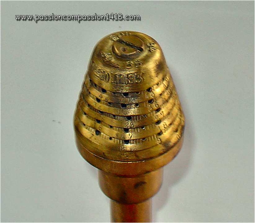
40/55 Mod 1880/93 time and percussion fuze. Markings '40-55 - ECP 94 - Mle 80-M93'. |
||
 |
||
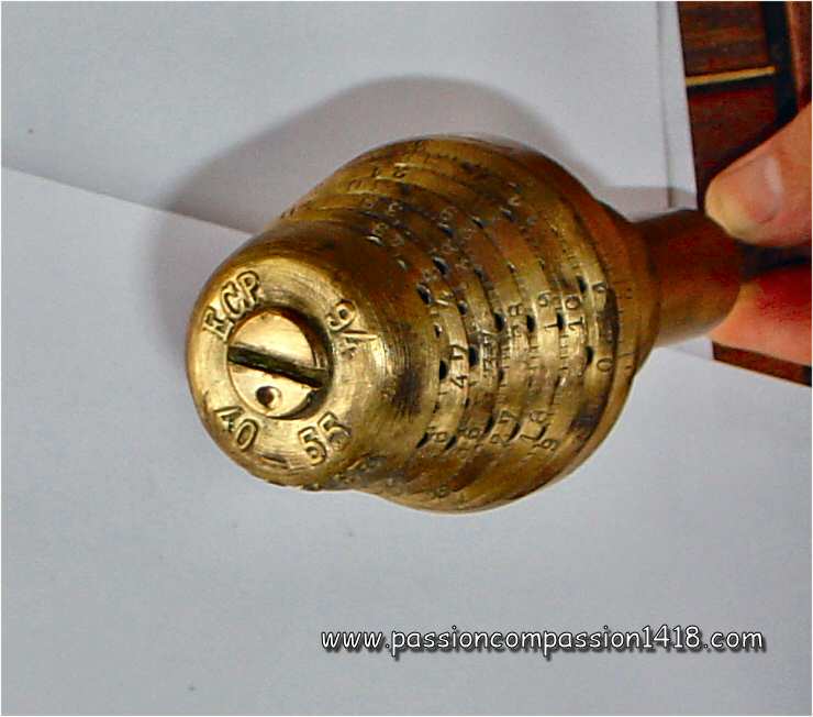
40/55 Mod 1880/93 time and percussion fuze. This strange piece probably was used for instruction purposes, and fixed on a long steel nail. The 40 mm tail thread has been replaced or covered by a smooth brass section, but the typical long tail of the Siege et Montagne percussion systems is subsisting. |
||
 |
 |
|
40/55 Mod 1880/93 time and percussion fuze. Graduations from 0 to 49. No stud observed. |
40/55 Mod 1880/93 time and percussion fuze. View from behind |
|
Return at the top of the page |
||
22/31 Mod 1897 time and percussion or Mod 1916 time fuze |
||
 |
This 22/31 Mod 1897 time and percussion fuze, based on the typical French tubular spiral type fuzes, was specifically designed at the destination of the rear charge shrapnell shells of the famous 75 mm Mle 1897 fieldgun.
Graduated from 0 to 24 seconds for the time behavior (that was ignited by the concutor housed inside the head axis room), the time flight setting before explosion being chosen by punching a hole on the graduation with the help of a specialised machine named 'débouchoir double'. This machine allowed a much quicker setup of the fuzes before shooting than when this operation was made manually, and therefore an essential part of the incredibly fire rate of the revolutionary 75 French gun. In order to be compatible with it, the fuzes had to be equipped with a reference stud located on the ring at the base of the graduated cone. The models manufactured after the start of WW1 didn't even had the intermediate graduations between the pre-drilled holes, since reading these marks was unnecessary with the use of te 'débouchoir'. The percussion systeme of this fuze designed to make the shell explode at impact was a 'Saussier' percussion system. Only meant to communicate the flame to the rear charge of the shell through an axial tube (called 'tulipe'), the fuze was not equipped with a tail detonator. The 22/31 Mle 1897 time and percussion fuze was mainly in use with the shells of the :
In 1916, a purely time variant was introduced similar in shape to the mod 1897, but lacking a percussion system (externally not discernable). Called '22/31 mod 1916 time fuze', it was mainly in use with the shells of the :
The 22/31 fuze, in its 1897 or 1916 versions, is the time or time and percussion fuze that can be observed most frequently nowadays in former batllefields. |
|
22/31 Mod 1897 time or time and percussion fuze. |
||
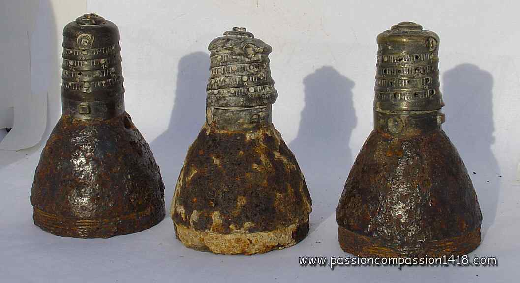 |
||
22/31 Mod 1897 time or time and percussion fuze. Three items observed in Champagne. The first one was punched for a 12,2 seconds time flight before explosion, the third at 17,3 seconds. Notibe the second one deformation under the effect of the landing energy. |
||
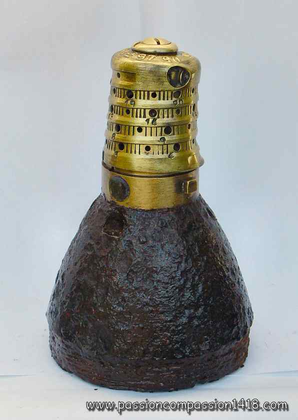 |
 |
|
22/31 Mod 1897 time or time and percussion fuze. Nice item, a typical artefact observed on former battlefields |
22/31 Mod 1897 time or time and percussion fuze. Hat top details. Markings'ECP 10 05' - '22-31 Mle 97' |
|
 |
 |
|
22/31 Mod 1897 time or time and percussion fuze. This item has been removed from the shell ogive, markings 'ECP 21 01 - 22-31 Mle 97 |
22/31 Mod 1897 time or time and percussion fuze. Rear view of two items; One of them still has its tail plug |
|
 |
 |
|
22/31 Mod 1897 time or time and percussion fuze. Sen from the ogive inner side with a view on the fuze vents communicating the flame to the rear charge through the shell axial tube ('tulipe') |
22/31 Mod 1897 time or time and percussion fuze. Wartime scheme |
|
Return at the top of the page |
||
24/31 Mod 1915 or 1916 time or time and percussion fuze |
||
 |
In 1914 the French Army did not have any kind of time fuse with detonator able to have a high explosive shell explode during their flight. This kind of fire, already in use in the German artillery, was useful against entrenhed ennemies, or against aircrafts, therefore it was decided to design an evolution of the 22/31 Mod 1897 time and percussion fuze, with a 24 mm tail thread compatible with the high explosive shells and the addition of a small tail detonator identical to the one used with the 24/31 Mod 1899 percussion fuzes with detonator.
The adaptation of a percussion system to the fuze body inspired from the 22/31 Mle 1897 was causing issues, so the first variant to be introduced was in 1915 the 24/31mm Mle 1915 time fuze with detonator. The tail inner room was containing no percussion system. It was in use with high explosive shells for AA fire (the lack of percussion behavior preventing the explosion of a AA shell whose time behavior had failed when it was landing on friendly territory). The fuze tail end was machined with a male thread allowing to screw a detonator. The time system hat was graduated from 0 to 24 seconds just as the one of the 22/31 Mod 1897 time and percussion fuze. The punching of holes from tye 0 to 2 graduations was made difficult in order to prevent the accidental and catastrophic explosion of the high explosive shells too close to the gun's muzzle out of the barrel. It was not before 1916 that the time and percussion variant was finally made available. In this one, the percussion system housed in the tail was a Robin system, from now on replacing the usual Saussier system from the older models. The percussion system was isolated from the time system by a shutter, so that it could not be triggered by it. A small 0.05 secods delay was systematically inserted into tail pyrotechnic chain to avoid the shell bursts inside the barrel. This version was called 24/31mm Mle 1916 time and percussion fuze with detonator, and it was mainly in use with the projectiles of the :
|
|
24/31 Mod 1915 time or Mod 1916 time and percussion fuze. The tail detonator is partly destoyed |
||
 |
 |
|
24/31 Mod 1915 time or Mod 1916 time and percussion fuze. Rear view of two items, on the side of the detonator thread (for female detonator) |
24/31 Mod 1915 time or Mod 1916 time and percussion fuze. front view, no visible markings |
|
 |
||
24/31 Mod 1915 time or Mod 1916 time and percussion fuze. Those two identical fuses only differs by the presence of a tin/lead protection cap (to remove before the shot) on one of them |
||
 |
 |
|
24/31 Mod 1915 time or Mod 1916 time and percussion fuze. Side view |
224/31 Mod 1915 time or Mod 1916 time and percussion fuze. Wartime scheme |
|
Return at the top of the page |
||
24/31 Mod 1916 or 1918 time or time and percussion fuze |
||
 |
The increase of the range of the 75 mm field gun, needed by the necessity to reach the highest possible altitudes in AA fire, but also thanks to the use of more aerodynamic shells, made the duration of the time system of the 24/31 Mod time fuze Mle 1915 or time and percussion fuze Mle 1916 too short for the full trajectory.
A purely time model, dedicated to the anti-aircraft fire with no percussion system in the tail, first appeared in 1916 : the '24/31 mm A Mle 1916 Time fuze with detonator' with a 'A' for 'allongée' ('Elongated'). This elongation of the spiral track was given by an additional spire (6 spires instead of 5), and the hat was tehrefore graduated from 0 to 31 seconds instead of the 24 seconds max of the previous models. In order to prevent catastrophic explosions of the high explosive shell too close from the gun muzzle, the punching of the holes was only possible from the 5 seconds one. The tin protection and the top nut of the time model were painted in blue. In 1918 a time and percussion fuze was derivated from this model by inserting a Robin percussion system in the tail and was named '24/31 mm A Mle 1918 time and percussion fuze with detonator'. In this one, a small 0.05 seconds delay was introduced in the pyrotechnic tail chain in order to prevent the high explosive shell explosion in the barrel, potentially destroying the gun and killing the servants. The tin protection of the time and percussion model was painted in white. It is easy to recognize that fuze thanks to the graduations going up to 31, but also by the thinner cone base, about half thick compared to the previous model. |
|
24/31 Mod 1916 time or Mod 1918 time and percussion fuze. |
||
 |
 |
|
24/31 Mod 1916 time or Mod 1918 time and percussion fuze. Model found in Champagne, with destroyed detonator |
24/31 Mod 1916 time or Mod 1918 time and percussion fuze. Two models, one of them still being covered by its tin/lead protection cap |
|
 |
||
24/31 Mod 1916 time or Mod 1918 time and percussion fuze. Tin/lead protection cap removed |
||
 |
 |
|
24/31 Mod 1916 time or Mod 1918 time and percussion fuze. Notice the cone base height difference between the elongated and regular models |
24/31 Mod 1916 time or Mod 1918 time and percussion fuze. Wartime scheme |
|
Return at the top of the page |
||
24/31 Mod 1917 or 1918 time and percussion or time fuze |
||
 |
Despite its increase to 31 seconds, the duration of the combustion of the 24/31 A time Mle 1916 and time and percussion Mle 1918 fuze with detonator was insufficient for the long ranges of the artillery of higher calibers than the 75 mm (and even for the 75 mm fielgun when its range was also upgraded). Consequently, a highly elongated model, with 9 fusing tube revolutions instead of 6, was designed.
That '24/31 mm LS Mle 1917 time and percussion fuze with detonator', with 'LD' for 'Longue Distance' ('Long Distance') was graduated from 0 to 51 seconds instead of the 0 to 31 seconds marks of the 24/31 A fuzes, and was equipped with a Robin-type percussion system in the tail. It was mainly in use with the projectiles of the :
|
|
24/31 LD time and percussion Mod 1917 or time Mod 1918 fuze. |
||
 |
 |
|
24/31 LD time and percussion Mod 1917 or time Mod 1918 fuze. Quite an impressive fuse by its length ! |
24/31 LD time and percussion Mod 1917 or time Mod 1918 fuze. Détail montrant l'orifice d'échappement des gaz de combustion du grain de poudre de sécurité, enflammé au départ. Orifice encore fermé par la feuille de laiton d'origine |
|
 |
 |
|
24/31 LD time and percussion Mod 1917 or time Mod 1918 fuze. Two items, one being covered by a tin/lead protection cap |
24/31 LD time and percussion Mod 1917 or time Mod 1918 fuze. Upper view, with the screw opening the igniting system |
|
 |
||
24/31 LD time and percussion Mod 1917 or time Mod 1918 fuze. Dismantled detonator to show the male thread of the fuse tail |
||
 |
 |
|
24/31 LD time and percussion Mod 1917 or time Mod 1918 fuze. Upper view of the item still covered by the tin/lead protective cap |
24/31 LD time and percussion Mod 1917 or time Mod 1918 fuze. Wartime scheme |
|
Return at the top of the page |
||
24/31 LDA Mod 1918 time or time and percussion fuze |
||
 |
To be exhaustive, we need to mention the design in 1918 of a '24/31 mm LDA Mle 1918 time and percussion fuze with detonator ' with 'LDA' for 'Longue Distance allongée' ('Elongated Long Distance'). Having 10 revolutions and graduated from 0 to 75 seconds, instead of the 9 spires and the 51 seconds max of the 24/31 LD time Mle 1918 and time and percussion Mle 1917 fuze with detonator version, this device fuse equipped the shells of the heavy artillery, and in particular of the ALGP ('Artillerie Lourde à Grande Puissance' - High Power Heavy Artillery).Their tin protection hat was painted in black with a green band at the base.
It was also built in a purely time version, without any percussion system integrated, and named 24/31 mm LDA Mle 1918 time fuze with detonator. In this case, the tin hat was still painted in black but the base band was blue. |
|
24/31 LDA Mle 1918 time or time and percussion fuze. The 10 spires version (below), compared to a 9 spires 24/31 LD Mle 1917 fuze (top). Picture Patrice Colin |
||
Return at the top of the page |
||
Time and percussion fuze Saint Chamond with two discs |
||
 |
Notable exception to the general use of revoluting fusing tubes for time fuzes in France, this Saint Chamond time and percussion 2-discs fuze was using the classical revolving discs system that was generalized in all the other armies. The lower disc was graduated from 1 to 18.
The St Chamond time and percussion fuzes were set by using a special apparatus named 'Regloir' ('regloir automatique sur banc à trepied') It was mainly in use with the projectiles of the :
|
|
Time and percussion fuze St Chamond with two discs. |
||
 |
 |
|
Time and percussion fuze St Chamond with two discs. Images courtesy Florian Garnier |
Time and percussion fuze St Chamond with two discs. One of the rare French fuzes using a revolving discs system |
|
 |
 |
|
Time and percussion fuze St Chamond with two discs |
Time and percussion fuze St Chamond with two discs |
|
 |
||
Time and percussion fuze St Chamond with two discs, disassembled |
||
Return at the top of the page |
||
22/24 mm concussion fuze for 37 mm tracer and incendiary shells Mod 1917 |
||
 |
The fight against balloons needed the use of special shells capable to ignite the fabric or the gaz of the aircrafts. Therefore, for the incendiary and tracer 37 mm shells, a dedicated very simple fuze was introduced. This 22/24 concussion fuze for 37 mm incendiary and tracer shells type D Mle 1917 of the Navy was a very lean device composed with a concussion system housed inside a brass ogive.
At the shell start in the barrel, a mobile inertia block bearing the percussion pin was propulsed backwards under the effect of the acceleration and the inertia, and compressed a safety spring. The percussion pin was hitting violently a primer cap whose flame was amplified by a compressed gunpowder ring. This was communicating the fire to a rooms made of a tin cylinder opened through the shell steel walls by 3 round windows and containing a wick. The combustion of this wick was acting as a delay that, once consumed, was igniting the shell's inner incendiary charge. The strong flames produced by this charge were projected to the outside of the flying and spinning shell through the 3 round windows during the shell trajectory in the air and hopefully through the balloon envelope. |
|
22/24 concussion shell. |
||
 |
 |
|
22/24 concussion shell. Top view on the head top screweed plug giving acess to the mobile inertia block bearing the percussion pin, and one of the 3 windows that were throwing flames during the shell flight. |
||
 |
||
22/24 concussion shell. The fuze is assembled with the 37 mm incendiary shell that has been separated from the propulsive cartridge. |
22/24 concussion shell. Modern scheme. |
|
Return at the top of the page |
||